Brushless Whoop Build – Part One

It took me a while to actually sit down and do the build for the brushless whoop parts that I got for Christmas.

The first thing I like to do on a new build is test the flight controller. Especially before any soldering is done, it’s good to make sure that the flight controller works, so that later on if it doesn’t I know that it’s because of something that I did and can troubleshoot it instead of wondering if I just got a bad one from the factory. It’s easy enough to do. Plug it into a USB cable to make sure it gets power, and then make sure that Betaflight will connect to it. Test out the gyro by turning and tilting the board and make sure that the movements match up with the animated diagram in Betaflight.

At that stage, it’s not critical to do, but since it’s already connected, I like to download the latest firmware and flash it to the board. It’s just a couple of steps to do, and isn’t any harder or easier to do now or wait until later. But since it’s already connected I figure why not.

The last step I took care of before really starting the build was binding my radio. I don’t always do this part so early, usually because for anything bigger than a whoop build, I don’t use a flight controller with a built-in receiver. So there’s some soldering that normally has to take place first. But in this case since the receiver is built into the board, it’s much easier to do now where the bind button is easier to get to, than to wait and do later.

Binding the radio took me a bit to figure out since I had to find the built-in receiver specifications. I couldn’t find anything about telemetry being available or not, but it would only successfully bind when I picked the radio setting without telemetry, so I’m guessing it’s not supported. Not a big deal for a small whoop like this, but something I’ll have to keep in mind if I ever decide I need to go hunting for it outside.

With the flight controller testing out of the way, I was ready to start figuring out the build. This involves dry fitting the flight controller to the whoop frame and trying to get an idea for where the canopy, camera, and VTX were all going to sit. I found the wiring diagrams for the flight controller on BetaFPV’s site, and used those along with the printed manual that came with the VTX to figure out how everything needed to be wired together.

The only part that wasn’t immediately obvious to me until I’d studied it for a couple of minutes was that the signal wire of the camera needed to go to the camera pad on the flight controller. This would apply the OSD information, and then a wire from the VTX pad to the video in pad on the VTX would take the signal for broadcast. I also didn’t need one pair of the 5V and ground wires on the VTX since the camera already had its own.

Once I figured all of that out, then I rechecked it by fitting all of the pieces together to make sure I knew which wires to cut, which to desoldering, and what was getting soldered to what. I could always fix any mistakes, replacing or lengthening any wires that I cut too short, but I didn’t want to have to mess with that if I could avoid it with a little extra care up front.

After checking a few times though, it’s usually time to just commit and do it and hope I’ve thought through everything I needed to. In this instance that included trimming all of the VTX wires to be just a bit longer than the camera wire lengths. Trimming the plug from the camera, which I wouldn’t need, and then desoldering the two wires from the VTX that I wasn’t going to need.

Desoldering is quite easy. It just requires me to get the piece set up where I can get some pressure on the wire that I’m trying to remove, so that I can have a minimal amount of time for the soldering iron on the board. In this case the extra 5V and ground wires that were going to be replaced by the corresponding wires on the camera.

After getting the wires cut to length, I was ready to tin the wires and the pads on the VTX and flight controller. Tinning just means to prep exposed wires and any copper pads on PCB’s that I’m going to be using with solder. Ideally so that when it comes time to solder a wire to a pad, I don’t have to add any additional solder, I can simple touch them together with a bit of heat and I’m done.

Soldering a small build like this is a bit of a challenge just because of the sizes of the pads involved. I’ve found using the lowest heat setting along with a lighted magnifying glass, and a very small soldering iron tip helps tremendously for this. I’ve also applied some tricks I picked up in painting miniatures for keeping my hands steady by moving the piece to the iron and keeping my arms are my sides.

Once everything has been tinned and then soldered together, the easy part is over. With the camera, VTX, and flight controller all wired up, it’s time to check for shorts and then plugin in a battery.

Before plugging in a battery and risking releasing the magic smoke, I like to use a multimeter and check that there’s no continuity between the various connections. For example the yellow wire from the VTX to the flight controller should have continuity between the ends, but if I touch a probe to one end and then touch the other probe to the ground then I shouldn’t have any connection. If I do it means there’s a short somewhere, and on a tiny build like this it’s probably because two pads are bridged.

In my case I did have a solder bridge on the VTX between the video signal and the ground. But that’s just a matter of adding some flux to the board and using a soldering iron to try to clean up the bridge. It only took me a couple of minutes to get it cleaned up in this case, and afterwards all of the connections passed the multimeter test.

Which brings me to the last part before assembly and that was plugging in a battery and testing that everything booted up, that the VTX was broadcasting, and best of all that I was getting an image through the goggles from the camera. It’s good to do all of that before assembling everything just to make sure that there’s no more soldering fixes that need to be made, and it’s a good chance to make sure I know which way the camera needs to go so that up is up.

Like Riding a Bike

I mentioned last time that I’d finally gotten my toothpick quad fixed, but too late to actually get it in the air. Looking ahead at the weather last Monday, I wasn’t expecting to be able to fly any time soon. But I hadn’t been paying attention to the sunset times, which had been getting later now that we’re into January. While 6:15 pm isn’t normally enough time for me to fly after I get home, not like during the spring and summer, I happened to be home by 5 pm last Friday. Even better was the rain we were supposed to get didn’t happen despite a heavy overcast, and the snow on the ground was hard and patchy enough that I didn’t feel it was too risky to rip a few battery packs.

I hadn’t flown since December 27th, so it had been almost exactly 6 weeks since I’d flown last, and I was a little unsure how comfortable I’d feel getting in the air again. I shouldn’t have worried though because aside from a little adjustment just after taking off, it was like I’d just flown the day before. I think there’s so much muscle memory involved in flying that it’s actually a lot like riding a bike, just more fun.

It felt so great to be back and flying outside. Flying inside is fun, but it’s not quite the same as being outside. I hadn’t realized just how much I’d missed flying until I landed at the end of that first pack, I couldn’t get the smile off of my face.

Besides just the fun of zipping around and doing flips and loops, I’m always fascinated by the change in perspective. I was particularly struck during this session be seeing how uniform all of the roofs were in the neighborhood where they all had snow still on the north facing sides and the south facing sides which got the sun throughout the day were all clean.

I was able to get three packs in, so about 12 minutes total time in the air, before I lost the light. It’s really reminded me of what I’ve been missing out on the last few weeks while I was putting of making repairs. I’m glad I was finally able to get back out there, but I wish I hadn’t waited so long.

HX100 Repair and Modification

I’m sad to say that it’s February and I haven’t flown at all yet this year. I could have been since my brushed whoop is flyable, but I kept waiting until I got my brushless whoop built. That quad is still in pieces on my hobby table. I keep thinking I’ll get it done over the weekend, but somehow they’ve kept passing by where by the time I’m ready it’s too late on Sunday night. I thought last weekend I’d finally get time to do it but I was laid up sick all weekend. So naturally this weekend was going to be the one, but one again things came up on Saturday that kept me from getting to work on it, and then Sunday I decided I needed to get my toothpick fixed first.

We had some unseasonably warm weather in Indiana over the weekend and I was pretty upset with myself that I couldn’t take proper advantage of it because my toothpick was still out of commission from the crash back in early December.

The Patient

I’d been putting this off because I wanted to fix the issue with the flight controller and the VTX not communicating properly while I did the motor repair, but I decided that I needed to just get the motor fixed and try out the antenna modification I’d been thinking about and leave the rest until later. That way I wouldn’t miss out on any more good flying days that might come along before summer gets here and I can expect some more consistent flying conditions.

Replacing the broken motor was pretty straight forward and only took me about 15 minutes. It’s the second time I’ve had to do this so I already had a good idea of the order of operations and things I needed to look out for. Remove the canopy, take the tape off of the motor wires, and remove the four nuts holding the flight controller down. Get the motor plug loose and pull the wires out, and then take the two mounting screws out to get the motor off of the frame.

After that it’s the same steps just in reverse. Mount the new motor with the same two screws. Tape the motor wires down, fish the motor plug through the slot cut in the foam that the flight controller is mounted on, and then get the plug seated. This part probably gave me the most trouble because I was trying to do it without taking the flight controller all the way off of the frame. That would mean cutting the zip ties holding the power leads and the receiver antennas to the frame, which isn’t a big deal, but I didn’t want to do all of that unless I had to. Thankfully a little fiddling with tweezers and I was able to get the plug seated.

With that done it was just a matter of getting the flight controller fastened back down, and taking the prop off of the old broken motor shaft and putting it on the new motor. Then plugging the quad into my computer and checking the motor direction in Betaflight.

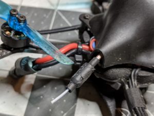
While I had the canopy off I wanted to try modifying how the VTX antenna was mounted. I mentioned back in my crash post that I needed to do something since I’d noticed that I was getting some damage to it from prop strikes. I’d already tried bending the antenna down a bit to keep it below the prop line but that didn’t seem to be helping. Also, I could have switched from the 65mm bi-blades back to the 2″ tri-blades that I was originally using but I like getting the extra flight time with the bi-blades, and besides I didn’t want to be limited in which size of prop I was using.

My idea was pretty simple. Because of the way the VTX was mounted in the canopy, I figured I could drill a hole just a bit above where the antenna currently stuck out and get an easy 30-45 degrees of uptilt on the antenna which would more than keep it out of the reach of the props. It just required doing a little dremel work and then fishing the antenna through before mounting the VTX.

This was my first time using the Dremel on plastic, and aside from a little slip which you can see above it went pretty well. I used a hobby knife and a file to clean up the hole afterwards and make sure there were no sharp edges to damage the antenna. But I’m surprised at how well this worked. It’s rare that an idea turns out exactly as expected, but I couldn’t be happier with how the antenna is coming out of the canopy now.

There should be no way the the props will hit the VTX antenna any more. I’m looking forward to getting it in the air and seeing how it flies now.