Building a Quad – Frame Change

After my first real flights ended with a broken battery lead and a fried flight controller and messed up video transmitter, I decided that since I was going to have to take everything apart anyway, I might as well change the frame I was using. While I liked the Phreak it really wasn’t suited well to having a four high stack, and rather than getting taller standoffs and screws to raise the top plate I decided to switch to an Acrobrat.

An Acrobrat is a 3″ frame designed with three mounting positions and a top-mounted battery, where the Phreak only had one mounting position and a bottom-mounted battery. That meant I could separate out the boards in the flight stack and have the camera and HD board up front, the flight controller and ESC in the middle, and the VTX and receiver in the back. Having the battery on top also meant I wouldn’t be landing on it.

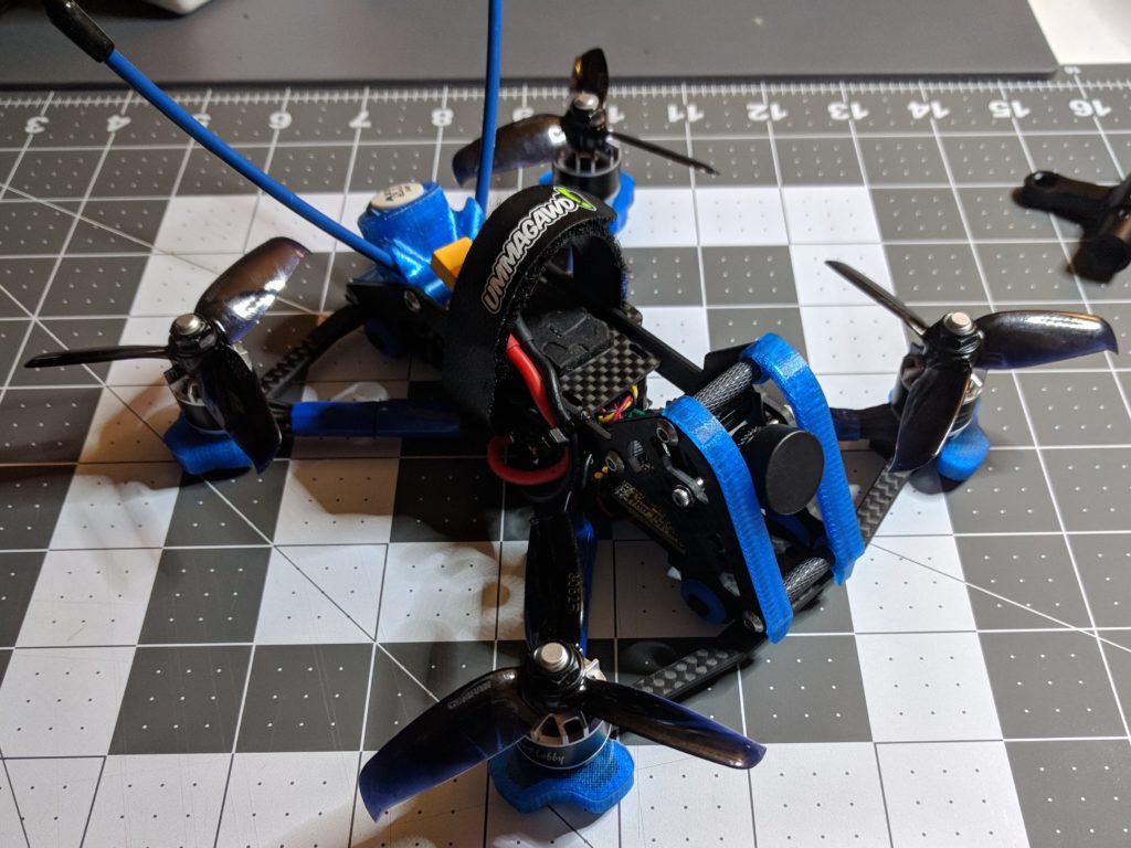
Since I was moving to a new frame, I also got a new set of 3d printed accessories from Brain3d. They had a nice kit that included arm guards, front bumpers, and a nice rear mount to handle both the VTX and receiver antennas.

Of course switching the frames meant taking everything off of the original and moving it over to the new one. But more than that, I had to lengthen the motor wires since the Acrobrat’s layout had a wider length from where the motors mounted to the ESC on the center stack. Fortunately I had saved all of the wire I’d originally trimmed, so it wasn’t too difficult to solder and heat shrink extensions on and retrim and solder back onto the ESC. I also decided to add a capacitor to the build to help smooth out any electrical noise, and taped it down to one of the arms.

With that done I was back to the original repairs I would have needed anyway. I soldered the wiring harnesses back up to the new flight controller board and reseated it on top of the ESC. Then I got the camera and VTX both hooked back up and mounted. The receiver I ended up loosely zip tying to the VTX, which I’m not sure was a good idea even with the Kapton tape to keep them electrically isolated but I haven’t tried changing that around yet.

While it didn’t take me as long as the original build it was still a few hours worth of work to move all of the electronics over to the new frame. I have to say that it was worth it though. It was much easier to fit everything in the Acrobrat than it was the Phreak, which just wasn’t designed to have that extra board in it for HD capture from the FPV camera.

Battery leads securely zip tied to the side-plate of the frame.

It took me a while to get to this point, but I’m pretty happy with the second iteration of my 3″ quad build. I have to put a 60% throttle cut on it in order to fly it around my yard, but that power is nice to have when I go to my in-laws farm or take it to a nearby park.

Building a Quad – First Flights and a Mistake

Can you spot the problem?

Having finished building my first quadcopter, I took it outside for a hover test and maiden flight.

For the hover test, I basically treated it like a live grenade. Setting the quad up on the driveway, gingerly plugging in the battery, and then sprinting away. Which is comical looking back on it now, but at the time I really had no idea what to expect. Before then I had already done motor tests without the props on, but something about having three inch spinning plastic blades had me erring on the side of caution. I armed the quad and throttled up until the quad lifted off of the ground and then I held it there for a few seconds before setting it back down. It didn’t flip out or anything, so it was time to actually fly it.

With my goggles on, I rearmed the quad and took it for a short maiden flight around my front yard. It was exhilarating but terrifying as well. At the time I just assumed it was because I was going from a small quad with brushed motors to a bigger one with brushless motors, and that I would get used to it after a period of adjustment. Regardless the maiden flight was good, although I didn’t really get a chance to push the motors much. I had wrapped up my build late and was pushing sunset as it was. I didn’t think it would be smart to take risks with a brand new quad especially when I wasn’t comfortable yet with the new size and additional power.

That weekend, we had a trip up to my in-laws farm for the weekend, which excited me since I’d have the chance to fly someplace where I wouldn’t have to worry about space or people or traffic. Although I did realize shortly after take off that I hadn’t paid attention to where the overhead power lines were, so I had to land and take my goggles off briefly to look around and map out what areas I wanted to stay away from. I had six batteries charged that I was looking forward to using.

The first flight went pretty well, and I was enjoying really getting to go full throttle with it. I was still pretty terrified of crashing it before I’d really gotten a chance to enjoy it much, so I was playing it safe and not trying out any rolls or flips or dives. But it was still a lot of fun to race over the fields and along the fences.

The second flight was great too. I was starting to relax a bit more, although not enough to start trying any tricks. It was really enough of a learning experience to adjust to the bigger weight and different type of motors, than to worry about doing any fancy flying.

Sadly there wasn’t a third flight.

I don’t know if it was the way I unplugged the battery after the second flight, or if it was a bad solder joint that was weakened by the vibrations during flight. But the red wire on the battery lead had come loose from positive battery pad and I didn’t realize it until I plugged the third battery in and I heard a popping noise. At first I didn’t realize what had happened so I unplugged the battery and plugged it back in again. Which is when I noticed that the red wire was loose from the pad, and quickly yanked the batter again.

I hadn’t release any magic smoke, and there was no visible damage to any of the electronics. I figured the electronics were fine and I would only needed to resolder the lead back onto the pad in order to have the quad working again. Of course it turned out to be a bit more of a struggle than that.

Once I got home, I resoldered the wire and plugged in the quad, but nothing happened. I then tried plugging it into USB and still couldn’t get any life from the flight controller. Despite there being no visible damage to the flight controller there was a short in the board somewhere. It turned out that while the ESC board was fine both the flight controller and the VTX were shot and had to be replaced. It was a $60 reminder about something I’d forgotten to do when building the quad, zip tie my battery leads.

In all of the buld videos I’ve seen the person doing the build always zip ties the leads to the frame after getting them soldered. This is incase the battery gets ejected in a crash that it won’t rip the pads right off the the board. Or in my case so that the joint isn’t getting pulled on. Even if it had been a bad solder join, had I zip tied the wires in place then it wouldn’t been moving around and possibly not even ruined any of the electronics.

Going back and looking at pictures from the original build, I actually think the ground wire joint looks worse than the positive does. The other thing I should have done better here was solder the wires at an angle so they were coming out along an arm without any sharp bending.

Building a Quad – Assembly

After picking the parts the first thing I did was take the flight controller and plug it into USB and connect it to Betaflight to check two things. First just to make sure that it powered up before I started doing any soldering on it. So in case I got a defective part I would be sure that it wasn’t something I did on the workbench that broke it, and I’d more easily be able to get a replacement. The second thing was to see if it was to record the firmware target that the flight controller was using and make sure it was the most recent firmware version.

Then next thing to do to prepare for the build was to flash the receiver with the most recent firmware version from FrSky. This was a new process to me and involved downloading the firmware from the vendor, storing it on an SD card that I inserted into my radio, and then plugging the receiver into the radio using a wiring harness that the receiver came, then flashing the firmware.

Finally it was time to start building the quad, starting with the frame. I’d already watched a video of a more experience builder putting one together, but seeing it done once and doing it yourself tend to be very different experiences. For fun and to try to stay organized, I started out by organizing all of the pieces.

There’s four arms, blue standoffs, a top plate, a pair of bottom plates that sandwich the arms, and miscellaneous screws. Putting it together wasn’t too much different from assembling a Lego kit or any of the various children’s toys that I’ve had to put together after a birthday party or on Christmas morning. I think it took me about 20 minutes to get the bottom plate and arms assembled and be ready to starting on installing the motors and the electronics.

Before I started installing any of the electronics, I needed to tin all of the pads, and I figured that would be easier to do before I put them on the frame. In all of the build videos I’d watched to get ready for this, the builder would just put the board on the frame and then add the solder from there, but I was coming into this with just a little bit of soldering experience and I wanted to give myself the best chance at success. So I laid out all of the boards in the flight stack and made sure I knew which wires ran to which pad.

Then I tinned all of the boards at once: flight controller, four-in-one ESC, and VTX. The Caddx HD capture board on the camera had plugs and didn’t need any soldering.

Putting the ESC onto the frame as the base of the flight stack and installing the motors marked the first real part of the build for me as the quadcopter started to take shape. The process itself was pretty simple: screw a motor onto an arm, run the motor wires to the ESC, measure and cut the wires, solder them to the ESC. But cutting wires like that was a bit nerve wracking for me, as I was paranoid about cutting the wires too short and too long. On the one side I’d end up without enough slack and have to solder additional wire back on along with heat shrinking the joint, and on the other side I was trying to have a clean build plus extra wire would also contribute to extra weight. Which a few grams doesn’t sound like a lot but for a small 3″ build like this every gram counts.

After that the next step was the battery lead. As often seems to happen to me with this hobby, the part I was thinking was going to be easy turned out to be pretty difficult. It took a lot of work for me to get these two leads soldered onto the main battery pads of the ESC board. The heavy gauge wire and the big soldering pads on the board required a lot more heat than I’d been using up until now in order to get the joints flowed together properly.

Soldering the rest of the electronics was pretty easy. The hard part had been getting the documentation online for the various parts and making sure I knew which pads to use on the flight controller for the camera and the VTX. It had a pin header that plugged straight into the ESC board which made assembling the rest of the flight stack pretty easy.

Then came the big moment, plugging in the battery for the first time to see if it all worked. After going over all of the solder joints with a multimeter to see if I had shorted anything, I took the battery and plugged into a smoke stopper before plugging that into the battery lead on my new quadcopter. A smoke stopper is basically a fuse that will trip in the case when there’s a short somewhere so that you don’t release the magic smoke from the electronics. I’d bought one with a light and a reusable fuse at the same time that I ordered my parts.

The smoke stopper lit up green and the leds on the flight controller, receiver, and VTX are lit up as well. The best part though was hearing the startup tones playing as the flight controller and motors synced up.

After the battery test I connected it to my computer and went into Betaflight to check that all of the motors were spinning the right direction, and then change the settings on the two that weren’t. Then I plugged in a battery again and I checked that my radio would connect, and that I was getting a video signal in my goggles from the VTX.

At this point I figured I was just about done, I just needed to put the top plate on and the props. Which naturally is when I ran into the one problem that gave me the most trouble in the whole build.

When I picked out all of the parts, I remember adding up all of the heights to make sure that it would fit inside the frame. But I was looking at the height of the standoffs on the frame and not the length of the screws for the flight stack which were a couple of millimeters shorter. That makes sense to me now since you don’t want those touching the top plate and transferring impacts from the top plate into the flight stack, but it meant that I was just a couple of millimeters short on getting the top plate on my brand new build.

It took more time rearranging the parts and trying difference spacers between the boards to get everything to fit than it did to do the whole rest of the build, or at least that’s what it felt like to me, but in the end I did manage to squeeze everything in. I wasn’t completely happy with the solution but it would do until I could order slightly taller standoffs and longer stack screws.

Building a Quad – Picking the Parts

With the weather warming up I started looking into building a larger sized quad to fly outside. I decided I didn’t want to go straight to a full sized quadcopter with 5″ props which is the standard for FPV freestyle. I wanted to be able to fly comfortably in my yard, so that I could get more time in during the week, rather than always having to go to a field or park. So I settled on a 3″ build plan, because I’d heard that building for smaller props than that wasn’t as good of an experience.

Build a quad from scratch was a daunting experience because of all of the different pieces that needed to be selected and work together. You have to decide on a frame, what size of motors, the camera, the video transmitter (VTX), the receiver, the antennas, the props, the electronic speed controllers (ESCs), and the flight controller. Each component has an impact on the others too. There’s the obvious factor of the weight of the different components versus the thrust that the motors and props will generate, but also just compatibility between the amount of space in the frame for components and the mounting pattern versus the size of the flight controller and other electronics.

I started with the motors and got some advice from some local pilots to look at 1407’s as a good size for flying 3″ props. Then I used a site called RotorBuilds to figure out the rest of the parts list. It’s a site where people post their quadcopter builds. Some with detailed articles and photo albums of the step-by-step and others with just a short description of how it flies. But all of them have a parts list with links to vendors on them. So I ended up searching the site by the size of motors I was looking at building with and getting ideas from that on what parts I was going to buy. One build in particular I ended up being interested in was a 3″ Xilo Phreak because the guy mentioned how durable it was, and I figured as someone just starting out that getting a quad that could handle some hard crashes would be a good idea. I also liked that the Phreak frame had replaceable arms, so I figured in a worse case scenario if I crashed and broke one I wouldn’t have to rebuild the whole baseplate.

For the flight controller, I ended up going with the one mentioned in that RotorBuilds parts list. The HGLRC stack came as a combo with a four-in-one ESC and a VTX so I didn’t have to worry about them working together and the price on the full stack was just a little cheaper than what I’d have spent on separate boards.

When looking at cameras, the major factor in picking one was that I wanted to do HD capture from this quad, and a 3″ build though is too small to carry a GoPro. Plus there was the fact that I didn’t own a GoPro and I didn’t feel like spending a couple hundred dollars to get one. So I had only two choices: a RunCam Split or a Caddx Turtle. Both of these are camera and HD capture board pairs where the camera signal passes through the board first for recording, then goes to the flight controller to get the onscreen display overlay, and lastly goes to the VTX. This allows capturing HD quality video to an SD card on the quad without any analog transmission, but adds some latency to the signal. Latency is a big point of contention among pilots. It is the amount of lag between the camera on the quad capturing an image and that image showing in the pilot’s goggles. Some people seem to be able to notice and be bothered by tiny amounts of latency in that setup, and try to stay away from these types of split capture boards. I’ve never really noticed a problem with it though. I picked the Caddx because it came in black and was a slightly newer design.

The receiver and antennas were that last parts and those were pretty much a given. Since my radio uses the FrSky protocol, and I wanted telemetry on the quad, I only had one option in the R-XSR. For the antennas I had an omni and patch Axii on my goggles already so I got another omni with the same polarization for the quad build.

I was doing all of this near Easter so many of the sites were running sales. I ended up getting most of the parts from GetFpv.com. They didn’t have the receiver in stock though, so I ordered that plus a couple of batteries and a smoke stopper from RaceDayQuads.com. Then I just had to wait for everything to show up.

Here’s the final parts list: